Existing Compressed-Air Systems
There are more than 630,000 compressed-air systems in the United States running an average of
5,476 hr and consuming more than 91 billion KWH
of electricity per year. With a total installed horsepower
of 32.5 million, this equipment consumes
$4.2 billion of electricity per year.
Compressed-air electricity consumption
represents 2.66 percent
of the electricity consumed
by all sectors in the United States.
Table 1 is a summary of industrial-sector electricity
consumption.1 The industrial sector, which
comprises manufacturing and non-manufacturing
industries, accounts for 31.7 percent of the electricity
consumption in the United States. As can be
seen in the table, the manufacturing industry
consumes the bulk (85 percent) of the more than
1 trillion KWH of electricity used by the industrial
sector. The table includes a summary of the potential
energy savings of motor-driven systems in
the manufacturing industry, assuming a simple
payback of less than three years. The savings
for compressed-air systems alone is more than
$714 million a year, a reduction of 17 percent.
This equates to an annual average savings of $1,133
for each compressed-air system.
It is important to note that compressed-air
systems account for 15.8 percent of manufacturing-
industry electricity consumption. Compressed
air is used to spin tools, drive cylinders and linear
activators, atomize paint and other liquids, clamp
work in place, clean hard-to-reach areas, drive
piston air motors, blow soot, and fluidize fine
particles. In addition, it is used in material handling
and separation, grinding and drilling,
pneumatic control, and sandblasting,
among other applications.
The Compressor
To achieve an energy-efficient compressed
air design and desired air quality,
many factors must be considered. The
first and perhaps most misunderstood is
the compressor. Compressors are devices
that raise fluid pressure by more than
5 psig or increase the density from inlet
to discharge by more than 7 percent.
There are two basic types: positive displacement
(reciprocating or rotary) and
dynamic (centrifugal or axial). Both are
volumetric-flow devices.
Positive-displacement compressors entrap
a volume of air and reduce it. Characteristics
are constant flow and variable
pressure ratio for a given speed. Dynamic
compressors, on the other hand, depend
on motion to transfer energy. Flow is
continuous. The volumetric flow varies
inversely with this differential pressure
across the compressor.
When used in a tool, compressed air
supplies force. Force is equal to mass
times acceleration; therefore, the work
performed by a tool is dependent on the
mass flow of air through the tool. The
underlying factor in specifying compressor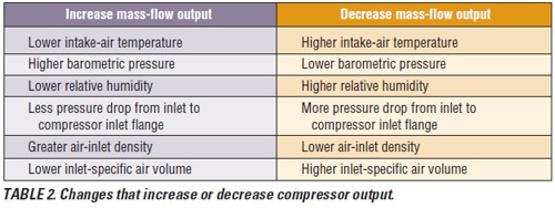 capacity, then, is the mass flow of air
delivered by the compressor. The following
equation relates volume flow to mass
flow:
capacity, then, is the mass flow of air
delivered by the compressor. The following
equation relates volume flow to mass
flow:
m (lb wet air per min) =
ACFM (cu ft wet air per min) x
density (lb wet air per cu ft wet air)
The problem is that compressors are volumetric devices; therefore, their output
is influenced by changes in inletair
density. Air-density (pounds per cubic
foot) variation is caused by changes
in barometric pressure (and/or gauge
pressure), air dry-bulb temperature,
and water-vapor content (relative humidity).
Table 2 lists some of the changes
that increase or decrease compressor
output.
volumetric devices; therefore, their output
is influenced by changes in inletair
density. Air-density (pounds per cubic
foot) variation is caused by changes
in barometric pressure (and/or gauge
pressure), air dry-bulb temperature,
and water-vapor content (relative humidity).
Table 2 lists some of the changes
that increase or decrease compressor
output.
Compressors installed at higher
elevations above sea level (or lower air
densities) get less air in each cubic foot
of intake air than they would if they
were installed at sea level. Table 3
presents performance data on ambient
airflow into and out of a rotary screw
compressor installed at sea level and at
10,000 ft above sea level. Note that the
ACFM-at-the-inlet and FAD flows
are only 1.38-percent lower at 10,000 ft,
even at a much lower inlet-air density.
This illustrates the compressor's ability
to hold its intake-volume flow rate.
There is, however, a significant change
in the mass-flow rate at 10,000 ft: The
mass flow into and out of the compressor
is 1,798.83 lb of dry air per hour, which
is 65.5 percent of the flow at sea level
(2,747.60 lb of dry air per hour). Like-
wise, the CAGI-SCFM at 10,000 ft is
65.5 percent of the CAGI-SCFM at sea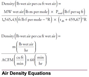 level because it is a type of mass-flow
term. Note that compressor-discharge
ACFM also is significantly lower at
10,000 ft. All of this illustrates that mass
flow is related to air density, as well as
volume flow, and that the mass flow into
a compressor is equal to the mass flow
leaving the compressor, provided there
is no leakage.
level because it is a type of mass-flow
term. Note that compressor-discharge
ACFM also is significantly lower at
10,000 ft. All of this illustrates that mass
flow is related to air density, as well as
volume flow, and that the mass flow into
a compressor is equal to the mass flow
leaving the compressor, provided there
is no leakage.
Another loss attributed to humidity is
that of water-vapor mass flow, 85 percent
or more of which is removed by intercoolers,
aftercoolers, and dryer systems
as it enters a compressed-air system. The
compressor, then, should provide the
amount of mass flow required for the
worst-case scenario, which is a hot, humid
summer day with a low barometric
(and/or gauge) pressure. In most cases,
the predominant factor influencing compressor
output is inlet-air temperature.
When there is a significant drop in
inlet-air density (such as with the compressor
installed at 10,000 ft in Table 3),
the ACFM at the compressor intake
usually does not change much. According
to the above equations, to compensate for
the reduced air density and unchanged inlet
ACFM, the inlet mass flow must drop.
Because discharge mass flow is equal to
inlet mass flow (when there is no leakage),
this means that the discharge mass flow
must drop as well. This helps to explain
why the compressor at 10,000 ft in Table
3 had a significant drop in mass flow
(inlet and discharge) and CAGI-SCFM.
Performance Technologies
To better understand compressorsystem
sizing, engineers need to know
how compressor manufacturers specify
capacity with ACFM, ICFM, FAD, and
SCFM performance figures. These performance
terminologies have frustrated
engineers for many years. This section
will provide definitions, examples, and
equations intended to eliminate any
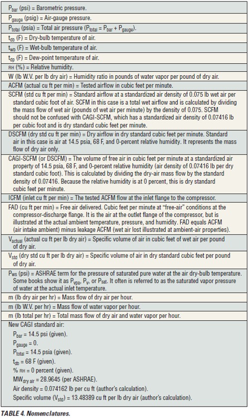
confusion. A list of nomenclatures that
will be used in this discussion is provided
in Table 4.
Figure 1 is a piping diagram of a compressor
system and aftercooler. Below the
diagram are the actual psychrometric
air properties and airflows. Above the
diagram are the actual conditions converted
to the psychrometric properties at
the air-intake air properties.
A lot can be learned by following the
mass flows in Figure 1. Mass flows, unlike
ACFM flows, are not affected by changes
in pressure or temperature (or water
vapor, in the case of dry-air mass flow).
The mass flow of dry air will remain
unchanged from inlet to discharge unless
there is leakage or loss attributed to
the use of pneumatic controls. CAGISCFM—
what the author prefers to call
DSCFM—is a type of dry-air mass flow
converted to dry standard cubic feet per
minute. DSCFM represents only the dryair
mass flow at the compressor-discharge
flange, the discharge mass flow after leakage.
In Figure 1, however, DSCFM flows
are provided at all points to reinforce
that they, like dry-air mass flows, do
not change unless there is leakage or loss
attributed to pneumatic controls.
It is important to note that the definition
of CAGI standard air has changed.
The new standard-air properties are
listed in Table 4. Figure 1 provides a few
equations that can be used to calculate
CAGI-SCFM flow.
Compressed-air-industry ICFM was
developed to avoid the confusion caused
by variable standards. This flow expresses
compressor inlet volume in terms of
actual inlet pressure, temperature, and
humidity. The problem is that ICFM can
be calculated at barometric pressure or
air-inlet-flange pressure, which is approximately
0.30-psi lower than barometric
pressure. Figure 1 calculates ICFM at
the inlet-flange pressure, as well as at the
inlet-flange dry bulb and humidity,
which are the same as the ambient dry
bulb and humidity. The ICFM flow is
1,021 cu ft per minute. If we calculate
the ICFM at the ambient total pressure
of 14.7 psia (instead of 14.39 psia), the
flow will be the same as the ACFM at
ambient, or 1,000 cu ft per minute. The
ACFM value will change as air density
changes because of variations in pressure
and temperature. The mass flows of dry
air and/or water vapor will not change
unless there is leakage, use of pneumatic
controls, or condensation.
The compressor manufacturer must
state the following psychrometric properties
of the ICFM flow:
• Barometric pressure (psi).
• Gauge pressure (psig).
• Total pressure (psia).
• Dry-bulb temperature.
• Relative humidity or humidity ratio.
 • Air density (pounds of wet air per
cubic foot of wet air).
• Air density (pounds of wet air per
cubic foot of wet air).
• Specific volume (cubic feet of wet air
per pound of dry air).
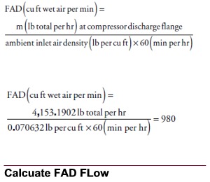
FAD also is a compressed-air-industry
term. It is the total moist airflow (dry air
and water vapor) discharged from the
compressor. Although FAD airflow is
expressed in cubic feet of wet air per
minute, it is not the actual ACFM at the
compressor discharge flange. In Figure 1,
the actual ACFM is 141 cu ft per minute.
The FAD airflow is a representation of
the actual mass flows of dry air and water
vapor, but expressed at the inlet-air
psychrometric air properties. In this case,
it is very important to understand the
psychrometric air properties chosen to
represent FAD airflow. In Figure 1, it is
the inlet-air conditions shown at the start
of the diagram (14.7 psia, 95 F, and 60-
percent relative humidity).
ACFM is the actual cubic feet per
minute of wet airflow (dry air and water
vapor) as determined by a Pitot-tube
traverse of the duct or pipe. In Figure 1,
the two-phase inlet airflow of 1,000
ACFM is made up of 966.77 cu ft per
minute of dry air and 33.23 cu ft per
minute of water-vapor flow. About 85
percent of the volumetric water-vapor
flow will be removed by the aftercooler
and refrigerated dryer, which will reduce
the amount of compressed air available
for use. To convert the ACFM flow to a
new set of psychrometric air properties,
use the following equation:
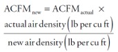
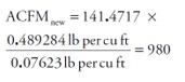
Using Figure 1, take the
ACFM at the compressor discharge
(141.4717 ACFM),
and convert it to ACFM at
the inlet-air properties:
Air leakage through shafts,
seals, and purge systems
usually is not discussed by
compressor manufacturers.
We also may have some
air usage for, say, pneumatic
controls. This would, of
course, reduce the compressor
FAD or the CAGISCFM
at the discharge of
the compressor. Figure 1 assumed
a loss of 2 percent.
The loss is 82.9849 lb of
dry air per hour and 1.7741
lb of water vapor per hour, or
20 ACFM at ambient air
properties.
[ back to top ]
Reference
1) Xenergy Inc. (1998).
United States industrial electric
motor systems market opportunities
assessment.
Compressed Air Systems Part 2:
Eliminating the Confusion
by William G. Acker
Eliminating the Confusion. Understanding the differences between ACFM,
ICFM, FAD, and CAGI-SCFM for improved
system design and equipment selection
Part 1 of this article reviewed the compressor-
performance variables ACFM (actual
cubic feet per minute), ICFM (inlet cubic
feet per minute), FAD (free-air delivery), and
CAGI-SCFM (Compressed Air &
Gas Institute standard cubic feet
per minute). Discussion was limited
to the compressor and aftercooler
portions of compressed-air systems.
This month, that discussion expands. Figures 2a
and 2b (pages 38 and 40) represent a complete
diagram of a compressed-air system and refrigerated
dryer, showing all energy, dry-air, and watervapor
flows; the lube-oil circuit; lube oil in the
compressed air and heat recovery; and heat into
the plant.
The rotary screw compressor in the diagram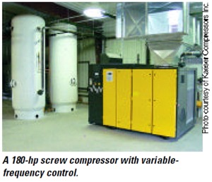 consumes 80 KW (273,020 Btuh) of electricity
at the compressor. The motor radiates 15,016 Btuh
of heat into the building, while the belt drive
radiates 7,740. The remaining 250,264 Btuh
is shaft power delivered to the compressor. The
compression of air picks up 70,163 Btuh, while
the lube oil picks up 180,101 Btuh. The air-cooled
aftercooler in Figure 2a is designed to remove heat
from the lube-oil and compressed-air circuits, as
well as motor heat and the heat of condensation. In
this illustration, the heat released into the building
is 256,475 Btuh, which could be used to preheat
boiler makeup water or outside makeup air. As a
rough rule of thumb, a 50-hp compressor at full
load rejects approximately 126,000 Btuh.
consumes 80 KW (273,020 Btuh) of electricity
at the compressor. The motor radiates 15,016 Btuh
of heat into the building, while the belt drive
radiates 7,740. The remaining 250,264 Btuh
is shaft power delivered to the compressor. The
compression of air picks up 70,163 Btuh, while
the lube oil picks up 180,101 Btuh. The air-cooled
aftercooler in Figure 2a is designed to remove heat
from the lube-oil and compressed-air circuits, as
well as motor heat and the heat of condensation. In
this illustration, the heat released into the building
is 256,475 Btuh, which could be used to preheat
boiler makeup water or outside makeup air. As a
rough rule of thumb, a 50-hp compressor at full
load rejects approximately 126,000 Btuh.
The aftercooler removes a significant amount of
the water vapor drawn in at the air intake. In
this case, the aftercooler removes 51.4 percent of
the water that enters the compressor system. This
is a significant amount that the refrigerated dryer
will not have to remove.
The refrigerated dryer has an
air-to-air heat exchanger, or what
some call a reheater. The reheater in
this case removes 10,909.60 Btuh
of heat from the compressed air before it enters the
refrigeration section of
the dryer. This significantly
lessens the burden
on the refrigeration section,
which removes
10,273.54 Btuh of heat
from the compressed air
itself. This heat is used to
elevate the dry-bulb
temperature of the leaving
air so that it is not
at 100-percent relative
humidity. The heat removed
by the reheater
also condenses 1.7587 lb
per hour of water vapor.
When the compressed air leaves the refrigerateddryer
section, the dry-bulb temperature is 37 F,
with a 37-F dew point (pressure dew point) and
0.000662 lb of water vapor per pound of dry air. To
get a feeling for the dryness of this air, air at sea-level
pressure would have to be at a dew-point temperature
of –7.2 F. To put it another way, if the air were
at 60 F, the relative humidity would be
at 6.1 percent, which, of course, is very
dry. The air-cooled-condenser section of
the dryer must remove heat from the
refrigerant, which is heat from cooling
the compressed air and heat from the
refrigerant compressor. The air entering
the air-cooled-condenser section then
picks up the refrigerant heat and fan
heat and discharges the total heat into
the building. The total heat removal
in this case is 19,497 Btuh, which is
dumped into the building. To make use
of this waste-heat energy, some plants use
water-cooled condenser sections, which
can be used to heat process water, or a
heat-recovery unit, which can be used to
supplement building heating.

Water-vapor removal in figures 2a and
2b occurs at the aftercooler, the reheater,
and the refrigeration section of the dryer
system. The amount of water vapor removed
by each section is listed in Table 5.
Water vapor entered the compressor at
a rate of 9.465 lb per hour. After all
removal, the rate was 1.6468 lb per hour,
a reduction of 82.6 percent.
The figures also illustrate the amount
of oil released into the compressed air.
This oil exists as vaporized oil and aerosol
(colloidal particles) oil. The total amount
released into the compressed air after
the air/oil separator is 0.0150 lb per hour,
or 6.0 ppm (mass). The oil in this example
is a mineral oil. Excessive foaming
in the compressor lube-oil circuit will
cause an increase in lubricant carryover
in the compressed-air stream. The annual
oil loss, assuming 8,400-hr-per-year
operation, is 18.4 gal. The oil-holding
capacity of this compressor is 22 gal, so it
will be necessary for maintenance crews
to replace the lost oil throughout the
year. The oil remaining in the air after
the high-efficiency coalescing filter is
0.00003 lb per hour; therefore, 99.8 percent
(0.01497 lb per hour) was removed
by the entire system. The coalescing filters
remove the aerosol oil in the compressed
air. Vaporized oil can be removed
by dropping the temperature of the compressed
air, which condenses the oil, or
by using a vapor-removal filter. One type
of vapor-removal filter is the activatedcarbon
cartridge filter bound in a nonwoven
polyester substrate.

The compressed-air system removes a
total of 7.8182 lb of water per hour and
0.01497 lb of oil per hour. In some cases,
the water and oil are collected in a central
collection-tank system and sent to
an oil/water separator. The oil in this
condensate is 1,991 ppm (mass), which
is too high a concentration for some
wastewater regulatory agencies. The
required maximum concentration discharged
to a wastewater-treatment plant
usually is 5 to 100 ppm (mass). Condensate-
separation systems are designed to
remove oil from water to meet wastewater-
code requirements.
Designing an energy-efficient compressed-
air system with adequate compressor
capacity is not easy. It requires the
elimination of excessive pressure losses
on inlet and discharge piping, filter systems,
coolers, and dryer systems. It also
requires the removal of contaminants,
such as water, oil, pipe scale and rust, and
air-intake particulate. To select a compressor,
an engineer first must identify
the SCFM usages and convert that
required flow to a mass-flow number.
This eliminates confusion over toolusage
SCFM and CAGI-SCFM. The
engineer then must identify the worstcase
air-intake psychrometric properties
to ensure adequate capacity on the worstcase
day. Having identified the required
compressor output, the engineer can
review bids, comparing units based on
efficiency, internal losses, power requirements,
total installed cost, and lifetime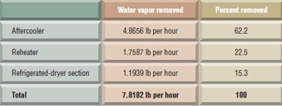 maintenance costs.
To ensure energy efficiency, pressure
drops must be kept low. Excessive pressure
losses from undersized or dirty
piping, filter systems, aftercoolers, and
dryers entail more brake horsepower
at the compressor and higher annual
electricity consumption. An excessive
pressure drop of 1 psi for a 1,000-CAGISCFM
compressor system will cost
more than $630 in added electricity
consumption a year. Therefore:
• Piping should be designed for 0.2 to
0.3 psi per 100 ft of pipe (or about 50 ft
per second).
• Filter systems should be carefully
selected, and all systems should be properly
maintained to reduce the demand
for electricity.
• Regulators should be properly
selected for systems that do not require
full pressure.
• Inappropriate uses of compressed air should be eliminated.
• Water-cooled compressors, watercooled
intercoolers and aftercoolers, and
oil coolers should be carefully selected.
• High pressure for compressed-air
tools, such as paint guns, grinders, and
sandblasters, should be avoided because
increased pressure above design pressure
only causes these tools to use more air.
Compressed-air control systems help
control pressure to plus or minus 2 psi.
• If the compressor building is of the
high-temperature, high-humidity variety,
the intake air should come from an
outside-air intake, which will reduce the
compressor brake horsepower and dryer
load, as well as the electricity consumption
of the compressor and dryer system.
Conclusion
The design steps taken during system
planning have direct effects on a system's
overall operation and maintenance;
therefore, it is important that an experienced
engineer and an experienced
compressor manufacturer be involved.
This will eliminate excessive operating
costs and operational problems.
[ back to top ]
Acknowledgements
The author wishes to thank the
following companies for their assistance
in the preparation of this article: Kaeser
Compressors Inc., Van Air Systems Inc.,
Airtek, Pneumatech Inc., and The Hankinson
Corp.
Bibliography
• Air Power USA. (2002). Energy savings in compressed air (11th ed.). Pickerington, OH: Air Power USA.
• Atlas Copco. (1999). Compressor installation manual. Atlas Copco.
• Van Ormer, H. (1989, January). Get better service from your packaged rotary compressor. Power, pp. 30, 31.
|
